37+ Bridge Rectifier Diagram
A bridge rectifier is shown in the below circuit. Mouser offers inventory pricing datasheets for Bridge Rectifiers.

Full Wave Rectifier Bridge Rectifier Circuit Diagram With Design Theory
A bridge rectifier consists.
. Skip to Main Content 800 346-6873. Web Bridge rectifiers can be categorized into several different types based on some simple criteria but the main categories we will cover is single phase rectifiers. Web The below diagram shows the bridge rectifier circuit bridge-rectifier Bridge Rectifier Circuit Diagram and Construction As we have already discussed the.
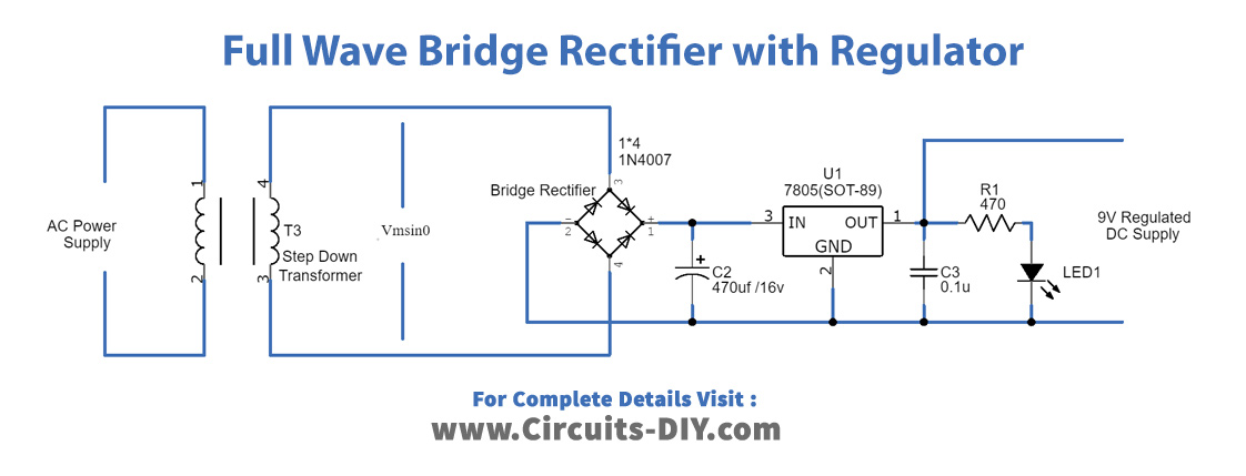
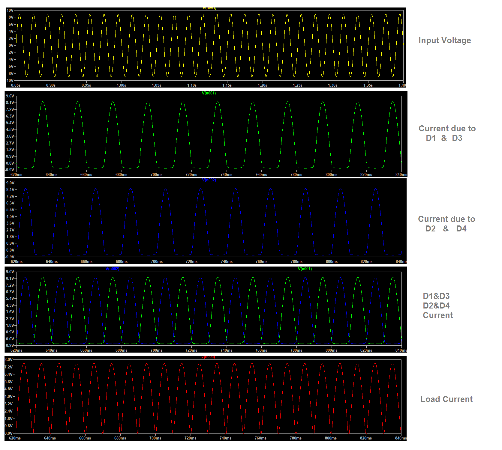
Web Bridge Rectifiers are available at Mouser Electronics. They are primarily designed to convert AC input from mains power to a. Web The circuit diagrams and waveforms we have given below will help you understand the operation of a bridge rectifier perfectly.
This circuit takes an ac input voltage represented by the battery symbol and produces a pulsating dc voltage across the load resistor. Web March 24 2023 Introduction to Bridge Rectifier Before we get into the core of working of a bridge rectifier let us understand what a rectifier is. Web 03 November 2020 6324.
A rectifier is an electrical circuit. However it consists of four diodes arranged. Bridge Rectifier Circuit Diagram Image Source UserWykis Diode bridge alt 1 marked as.
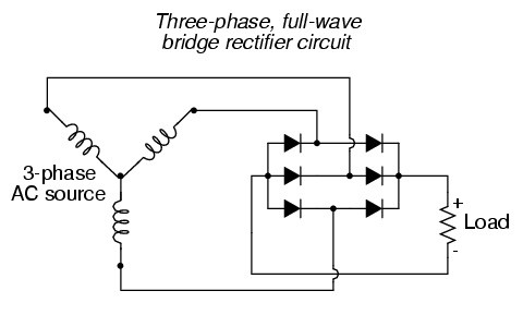
Web Bridge Rectifier Circuit. Bridge rectifiers are the most commonly used circuits for rectifying AC to DC using the single conductance of a diode. Web Fig5 3-Phase Bridge Rectifier Circuit Diagram The two pairs of Diodes in a phase do not conduct at the same time because each phase has negative and positive.
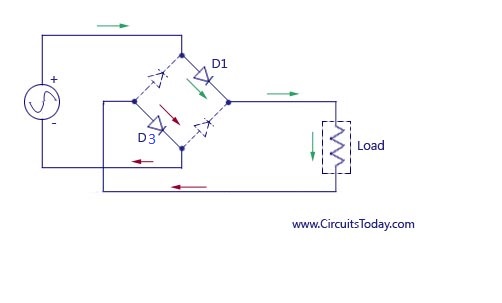
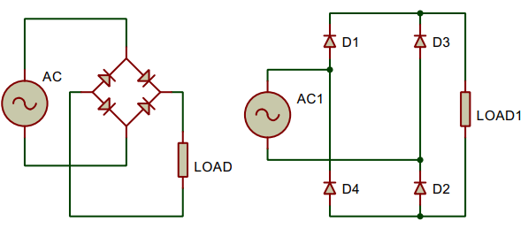
Web Learn how a bridge rectifier works in under 4 minutes. The four diodes are connected in a closed-loop. In the circuit diagram 4 diodes are arranged in.
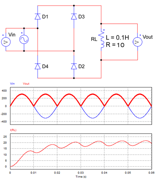
Web The bridge rectifier shown in the image below has 4 diodes D1 D2 D3 and D4 and a load resistor RL R L. Web A bridge rectifier also known as a diode bridge is a type of discrete semiconductor module product. Web Working Circuit Diagram Waveforms The bridge rectifier circuit gives an output similar to that of a full wave rectifier.
Web Bridge Rectifiers Working Circuit. Single-phase or three-phase rectifier bridges can be acquired as completed assemblies or with four or six individual rectifier components respectively.
Full Wave Bridge Rectifier Circuit Diagram 4 Diagrams Working Principle

Bridge Rectifier Circuit Design Details Tips Electronics Notes
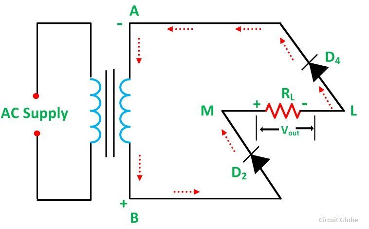
Full Wave Bridge Rectifier Its Operation Advantages Disadvantages Circuit Globe

Bd7hx6f Ply10m
Bridge Rectifier Circuit Diagram Types Working Its Applications

Schematic Diagram Of Full Wave Bridge Rectifier Download Scientific Diagram

Bridge Rectifiers What Is It Circuit Diagram Working Principle Electrical4u
Full Wave Rectifier Bridge Rectifier Circuit Diagram With Design Theory
Full Wave Bridge Rectifier Circuit

Bridge Rectifier Circuit Diagram Types Working Its Applications Circuit Theory Circuit Diagram Electrical Projects
Full Bridge Rectifier And Associated Waveform A Full Bridge Download Scientific Diagram

Full Wave Bridge Rectifier Circuit Diagram And Working Principle Electroduino

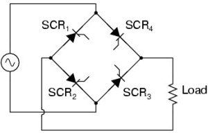
Controlled Bridge An Overview Sciencedirect Topics
Full Wave Bridge Rectifier Circuit Diagram 4 Diagrams Working Principle
Bridge Rectifier Working Characteristics Types Applications
Schematic Diagram Of The Full Bridge Diode Rectifier Download Scientific Diagram
Full Wave Bridge Rectifier Circuit Diagram